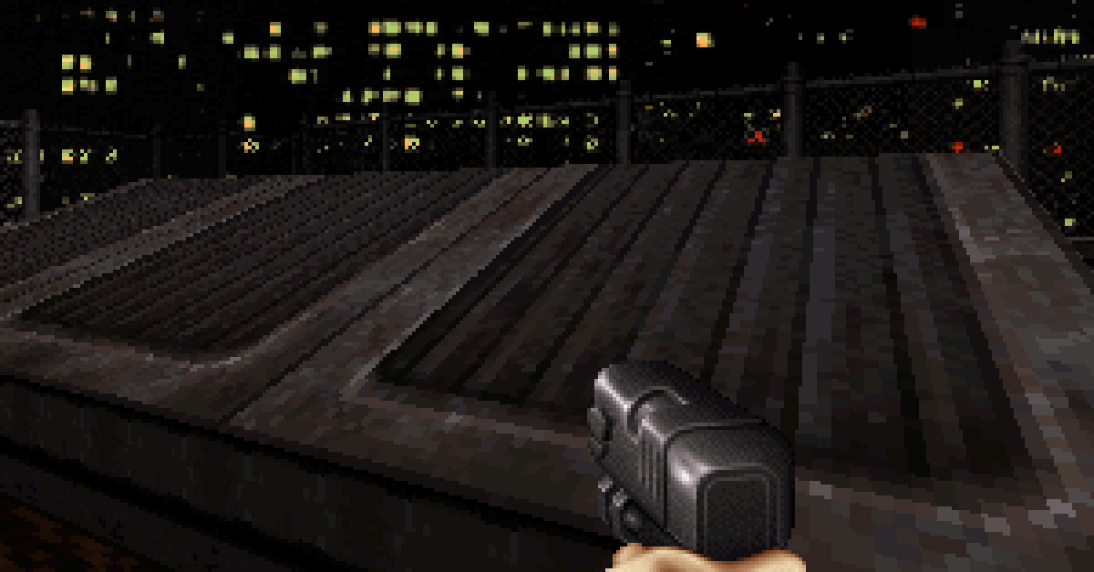
Disclosure: GPT wrote this article based on the author’s questions, technical guidance, and editorial direction. Its technical claims were checked against released Build and Quake source code, period processor manuals, and first-hand developer explanations. All sources are linked below.
How Duke Nukem 3D Made Perspective Texture Mapping Fast on a 486
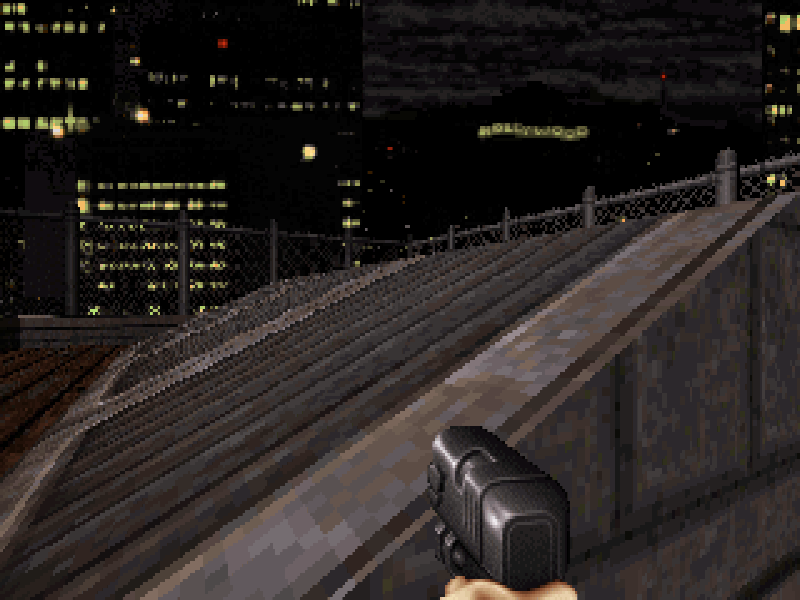
Sloped floors and ceilings are among the Build engine’s signature features. They also create a difficult performance problem. A level floor has a convenient horizontal constant-depth direction across the screen. A generic slope does not retain that horizontal constant-depth direction. If an exact perspective mapper draws that slope in ordinary horizontal strips, it must recover texture coordinates from a depth value that changes from pixel to pixel. A straightforward implementation would perform a reciprocal or division for every pixel.
That was an alarming prospect on the hardware Duke Nukem 3D was meant to support. Its published minimum processor was a 486DX2/66 in standard VGA modes. Floating-point division was slow on a 486, integer division was also slow, and even the much stronger Pentium FPU did not make division cheap.
The core question is therefore:
How did Build render perspective-textured slopes at a useful frame rate on a 486? Did it follow angled lines of constant depth, did it use periodic perspective division like Quake, or did it use another shortcut?
The answer in one paragraph
Build used a hybrid solution. It retained the vertical-column organization that already fit its wall projection and clipping system. For each visible slope column, the DOS assembly mapper obtained an approximate reciprocal at the bottom and refreshed it at intervals of no more than eight pixels. It did not calculate that reciprocal with DIV, IDIV, or FDIV. It normalized the denominator, consulted a 2,048-entry reciprocal table, used two integer multiplies to derive new u and v increments, and stepped those coordinates with fixed-point additions inside the block. Ken Silverman summarized the method himself as a reciprocal lookup and two multiplies every eight pixels, with linear interpolation between.
Build therefore did not use angled constant-Z rasterization for its slopes, and it did not pay for the periodic hardware divide used by Quake. It used the same broad idea of short projective intervals, but replaced the divide with a table-assisted reciprocal approximation.
Why this was a 486 problem
For a general textured plane, u/z, v/z, and 1/z vary linearly in screen space. Recovering u and v requires division by the interpolated 1/z. Performing that recovery at every pixel is the direct, accurate solution, but it was far too costly for a 1990s software renderer.
Intel’s 486 documentation lists a full-precision x87 FDIV at 73 core clocks. Reduced precision could lower that figure, but division remained a long operation. The original Pentium substantially improved floating-point performance, yet the familiar claim that its FPU was “five times faster” needs context. Intel reported roughly three times the overall floating-point performance for a 66 MHz Pentium versus a 66 MHz 486DX2. It said suitably scheduled and pipelined applications could reach five times or more, but its same-clock comparison put FDIV itself at only about 2.2 times faster. The five-times figure was an application-level opportunity, not a universal instruction ratio. These figures come from Intel’s Pentium Processor Family Developer’s Manual, Volume 3 and its Intel486 timing tables.
Quake was designed to exploit the Pentium’s particular strengths. Michael Abrash documented Pentium FDIV latencies of 39 clocks at extended precision, 33 at double precision, and 19 at single precision. Quake deliberately selected the faster single-precision mode and started the next division while the two integer pipelines drew the current subspan. The divide remained slow, but much of its latency could be hidden behind useful integer work. Abrash also stated plainly that this strategy helped on Pentium and hurt on 486.
The products’ published requirements reflect that split. The Duke Nukem 3D manual names a 486DX2/66 as the VGA minimum and a Pentium 75 as recommended. Quake’s shipping README requires a Pentium or better and an FPU. Its technical notes call sluggish 486 performance a known condition and display a turtle below 10 frames per second because that was not considered good gameplay.
This does not mean one texture divide explains the entire performance difference between the games. Quake renders an unrestricted six-degree-of-freedom polygon world, processes a different visibility system, combines textures with lightmaps, and performs extensive floating-point work beyond its span mapper. Build exploits a far more constrained world model. The comparison is still useful because it isolates two very different ways of paying for perspective inside a software texture loop.
How Build organizes the screen
Build is often casually described as a raycaster, but that description hides the structure that matters here. Ken’s own summary of the classic renderer says it collects facing walls into bunches, sorts those bunches, projects their endpoints, calculates their upper and lower screen edges, and clips coverage independently for every screen column. The renderer maintains a top and bottom boundary for each x-coordinate.
That representation naturally favors vertical work. Walls, sprites, masked walls, and slopes can consume visible vertical runs directly. Flat floors and ceilings are the exception: Build converts the remaining gaps between those vertical boundaries into horizontal spans because a level plane has a particularly cheap horizontal mapping.
This is similar to the surface specialization used by other upright-camera engines of the era, including Doom, but it should not be pictured as one scene ray filling each screen column. The important result is the same for this discussion: by the time floor and ceiling pixels are drawn, Build already knows their coverage as a collection of per-column top and bottom limits.
Constant depth is the easy case
The word “depth” needs a precise definition here. It means camera-forward distance, measured perpendicular to the screen. It does not mean Euclidean distance from the eye, and it does not mean Build’s map z-coordinate, which represents vertical height.
Ken explained the optimization directly: if both endpoints of a screen-space line are at the same camera depth, the projective denominator is constant along that line. One setup scale can serve the whole line, and the inner loop can advance texture coordinates linearly without division. His explanation identifies the two most important Build cases: vertical lines on walls and horizontal lines on level floors and ceilings.
Vertical walls
At one screen x-coordinate, a vertical wall column refers to one horizontal position on that wall. Its camera-forward depth does not change as the renderer moves up or down the column. The horizontal texture coordinate is fixed, while the vertical coordinate advances linearly. Under Build’s upright-camera model, this produces the required perspective mapping with no per-pixel divide.
Level floors and ceilings
For a horizontal world plane, the projective denominator depends on screen y but not on screen x. Every pixel in one horizontal screen row therefore shares the same camera-depth scale. Build’s ceilscan and florscan routines convert visible column gaps into horizontal spans. The hline setup selects a precomputed row-dependent reciprocal, derives u and v increments, and the assembly loop walks across the row using additions.
The texture coordinates are linear across that row because the projective equation simplifies for a level plane. This is not a whole-polygon affine shortcut. The depth scale changes from one row to the next, which preserves the visible perspective convergence of the floor or ceiling.
Could Build follow angled constant-Z lines?
This is a reasonable hypothesis. Intersect any textured plane with a plane of constant camera-forward Z and the result is a straight line. After projection, the constant-Z contours of one planar surface form parallel screen-space lines. Since depth is constant along each contour, its texture coordinates can be advanced linearly. The line’s inner loop needs no division, although setup still needs a scale or reciprocal for each contour unless those values can be reused or precomputed.
Silverman had explored this family of algorithms outside classic Build. In a 2024 interview he described POLYTEX as his first attempt to compete with Quake, and a later technical discussion identifies its renderer as a constant-Z experiment. That makes constant-depth traversal a natural possibility to consider for Build’s slopes.
The practical problem is raster organization. On a generic slope, the constant-Z contours are usually diagonal. Walking a diagonal line means noncontiguous framebuffer writes, additional edge and coverage bookkeeping, and an awkward conversion from Build’s top-and-bottom column limits. A staircase approximation to the diagonal can also create gaps, overlaps, or sawtooth behavior unless carefully repaired.
Ken later described constant-Z polygon mapping as a poor practical choice because it still produced artifacts and lost speed whenever the drawing direction was not horizontal. Most decisively, when asked whether Build slopes used constant-Z lines, he said no: classic Build drew them vertically and corrected the mapping every eight pixels.
How Build represents a slope
A Build slope is one mathematical plane clipped to a sector polygon. It is not a general mesh with an independent height at every vertex.
The sector stores a base ceiling or floor height and a signed slope value named ceilingheinum or floorheinum. The renderer uses the sector’s first wall, referenced by sector.wallptr, as the zero-rise or hinge line. Conceptually:
height at (x, y) = base height
                 + slope amount * signed perpendicular distance from the first wall
The actual calculation normalizes by the wall length and applies Build’s fixed-point scales. The released getceilzofslope, getflorzofslope, and alignment functions show the plane calculation.
The editor can change the hinge with Alt-F, but it does so by making the selected wall the sector’s first wall. The map format does not store a separate arbitrary hinge pointer. Ken documented that behavior when slopes were introduced in the Build development log.
From visible slope coverage to slopevlin
A generic slope no longer has the flat floor’s horizontal constant-depth property. Across an ordinary horizontal screen row, the projective denominator generally changes with x. Build could reorganize the surface into diagonal constant-Z contours, but doing so would discard the convenient vertical coverage already produced by its wall and portal system.
Instead, the engine dispatches a sloped floor or ceiling to grouscan. The function walks from left to right over screen columns. At each x-coordinate it obtains the visible y range from the clip arrays, prepares the shade lookup information, and sends that vertical run to slopevlin. The DOS mapper starts at the bottom pixel and moves upward through the framebuffer.
For a fixed screen column, the texture coordinates have the projective form:
u(y) = u base + u coefficient / D(y)
v(y) = v base + v coefficient / D(y)
The denominator D(y) changes linearly with screen y and usually also changes when grouscan advances to the next column. This expression is algebraically equivalent to intersecting a viewing ray with the plane. It does not mean Build changes into a general scene ray tracer. Projection, bunch sorting, portal traversal, and column clipping have already determined which part of the plane is visible.
Inside the DOS slope mapper
The active A.ASM implementation of slopevlin is where the central performance question is answered.
1. Normalize the denominator and look up its reciprocal
Before entering the assembly routine, grouscan passes an approximate reciprocal for the bottom of the column. The helper krecipasm does not execute a divide. It converts the signed denominator to a single-precision floating-point representation, uses high mantissa bits to select one of 2,048 reciprocal-table entries, uses the exponent to shift the result into range, and restores the sign.
This is not a raw table[depth] lookup. Floating-point normalization compresses a wide range of possible denominators into a small mantissa table, while the exponent supplies the power-of-two scaling.
2. Refresh the reciprocal every eight pixels
The assembly defines BITSOFPRECISION as 3, so its normal block size is 2^3, or eight pixels. It advances the denominator to the next block boundary, obtains another table-assisted reciprocal, subtracts the prior reciprocal, and performs two integer multiplies to derive the u and v increments for that block.
The inner loop draws no more than eight pixels with those fixed increments. A shorter block handles the remainder at the top of the column. In simplified pseudocode:
get the approximate reciprocal at the bottom of the column

while pixels remain:
    choose a block of no more than 8 pixels
    approximate the reciprocal at the next boundary
    derive fixed-point u and v increments
    draw the block using additions
Ken called this an approximation and said the full calculation every eight pixels was frequent enough to hide its artifacts. That accuracy tradeoff is a consequence of the method. The important performance result is that each block uses a table lookup and two multiplies instead of a hardware divide.
3. Reduce each pixel to integer address work
Inside a block, the mapper:
- adds the fixed-point u and v increments;
- forms a texture address with prepatched shifts and a mask;
- fetches one 8-bit texel;
- applies a shade and palette lookup; and
- writes one byte to the framebuffer.
There is no DIV, IDIV, or FDIV anywhere in krecipasm or the active slopevlin texture rasterizer. Other slope-related geometry and clipping functions are outside that claim.
4. Precompute slope shading by screen height
Texture coordinates were not the only challenge. Ken said shading was the trickiest part. Build generates a one-dimensional lookup that maps screen height to a shade-table pointer for the current sloped surface. Every column can reuse that table with a different starting offset. The inner loop therefore performs a palette lookup instead of calculating visibility and shade from scratch for every pixel.
How this compares with Quake
At a high level, the two texture mappers are closer than they first appear. Both split a projective mapping into short intervals, establish texture coordinates at interval boundaries, and step the coordinates linearly between those boundaries. Their crucial difference is how they obtain the next boundary value.
Quake’s software world mapper advances screen-space equations for 1/z, s/z, and t/z. In the released x86 code, d_subdiv16 defaults to 1, which selects D_DrawSpans16. That routine establishes a new projective endpoint every 16 horizontal pixels. Setting d_subdiv16 to 0 selects the more precise eight-pixel version.
Quake executes a real x87 FDIV for the upcoming endpoint. Its assembly starts that divide before drawing the current subspan, then uses the Pentium’s integer pipelines while the division remains in flight. It also lowers x87 precision specifically to make FDIV faster. Build’s DOS slope mapper performs no equivalent divide. It estimates the reciprocal from its table at boundaries no more than eight vertical pixels apart.
The phrase “bilinear texture mapping between corrections” mixes two different ideas. Both loops linearly interpolate texture coordinates inside each short interval. That is piecewise-affine coordinate stepping. Bilinear texture filtering would fetch and blend four neighboring texels for every output pixel. The classic software loops instead select one texel from the integer portions of the interpolated coordinates. Quake’s mipmaps and prelit surface cache are separate optimizations, not bilinear filtering in this span loop.
The comparison can be summarized as follows:
- Quake’s default x86 world mapper: horizontal 16-pixel subspans, a real reduced-precision
FDIVat each new endpoint, and deliberate overlap with integer drawing. - Quake’s optional finer-subdivision mode: horizontal eight-pixel subspans using the same general divide-and-interpolate strategy.
- Build’s DOS slope mapper: vertical blocks of no more than eight pixels, a normalized reciprocal-table estimate at each boundary, two integer multiplies per block, and no division in the texture rasterizer.
- Build’s flat floors and ceilings: full horizontal constant-depth rows, so periodic perspective correction is unnecessary.
This rasterizer comparison does not reduce the two engines to one performance difference. Quake’s full true-3D workload was much broader. It does show why Quake’s Pentium-oriented divide strategy was not the strategy Build chose for a feature expected to work on a 486.
The rest of Build’s optimization stack
The reciprocal table is the headline technique, but it works as part of a larger system.
Fixed-point coordinates and prepared tables
Build is overwhelmingly a fixed-point engine. Texture coordinates, increments, framebuffer row offsets, texture shifts and masks, palette conversions, visibility scales, and trigonometric values are prepared in integer or lookup-table form. The pixel loop is designed around additions, shifts, masks, indexed loads, and a byte store.
A small but important use of x87
The active slope path is not completely integer-only. krecipasm, setupslopevlin, and slopevlin use FILD, FADD, FST, and FSTP. The x87 stack holds or normalizes the changing denominator so its bit representation can drive the reciprocal lookup. It does not perform floating-point division.
That small dependency had a large consequence for a 486SX, which had no usable on-chip FPU. Without a 487SX coprocessor, those instructions had to be emulated in software. Ken later said he had used x87 to gain the equivalent of extra register capacity and regretted the resulting slope slowdown on 486SX systems. Duke’s documented minimum was a 486DX2/66, which did include an FPU. An integer-only slopevlin2 routine exists in A.ASM, but the released renderer does not call it.
Literal self-modifying code
Build uses self-modifying code in the strict sense. Before drawing, setupslopevlin writes new operands into selected instructions in the already assembled routine. Labels named slopmach1 through slopmach7 mark several patch sites. The values include the texture pointer, framebuffer stride, texture-coordinate shift counts, texture mask, and a displacement used to reach row-dependent shade data.
This is specialization, not a code generator that emits one instruction for every pixel. The per-pixel and per-block loops remain. Patching moves read-only values out of scarce general-purpose registers and turns variable operations into immediate ones. Ken’s own explanation of Build’s self-modifying code emphasizes register savings and the greater speed of immediate shifts compared with shifts through CL.
Instruction layout and Pentium pairing
The original Pentium could issue certain compatible and independent integer instructions together through its U and V pipelines. Build’s assembly aligns hot loops and interleaves independent coordinate, address, and framebuffer operations in a way that creates pairing opportunities. Integer multiplies and divides, and some shifts, had pairing restrictions, so pairing supported the algorithm rather than replacing it. Build’s larger win came from moving expensive work out of the pixel loop and avoiding division entirely there.
A measured result on period hardware
Ken’s development log contains a focused measurement from September 22, 1995. On a local-bus 486-66 in VESA 2.0 at 320×200, a full-screen slope improved from 24 frames per second to 35 frames per second after optimization. The next entry records further assembly work. This is a slope-rendering test, not a complete Duke Nukem 3D gameplay benchmark, but it directly demonstrates that the specialized mapper was practical on the intended CPU class. The result is recorded in BUILD2.TXT.
In 2024, Ken also said slope mapping might have been somewhat faster if he had found time to make it render horizontally. That comment should not be mistaken for saying a horizontal row on a slope has constant depth. It suggests that another coverage and memory-access organization might have improved throughput while still requiring projective correction.
The readable C translation
Ken translated A.ASM into A.C in June 1996 for Macintosh and console porting teams, then publicly released it in 2003. The C routine obtains a reciprocal for each pixel, which makes the projective relationship easy to read. It is not a cycle-for-cycle model of the optimized DOS assembly.
The C translation is therefore useful for understanding the equation and for portable source ports. The assembly and Ken’s direct explanation are the correct references for understanding how the original DOS slope mapper achieved its speed.
Conclusion
The performance puzzle has a precise answer. A generic slope loses the horizontal constant-depth rows that make level Build floors cheap. Build did not recover that property by tracing diagonal constant-Z lines. It also did not follow Quake’s approach of issuing a real floating-point divide every eight or sixteen pixels.
Instead, Build preserved its vertical column coverage, approximated a reciprocal from a compact table at intervals of no more than eight pixels, used two multiplies to derive fixed-point texture steps, and reduced the inner loop to simple integer address and palette work. Precomputed shading, lookup tables, self-modified operands, careful register use, and hand-arranged assembly completed the optimization stack.
The mapping contains the normal shortcuts of a fast software renderer, including table approximation and linear stepping within each block. Those details explain how the result was produced. The central fact is simpler: the DOS slope texture rasterizer achieved perspective without executing a hardware divide at all.
Primary sources and further reading
- Ken Silverman, “Build Slopes,” 2006: Ken’s direct answer about vertical rendering, one reciprocal lookup and two multiplies every eight pixels, linear interpolation, and approximation.
- Ken Silverman, “Build rendering,” 2006: wall bunches, column clipping, horizontal flat-plane spans, and vertical rendering for other surfaces.
- Ken Silverman, “Roll effect (rotation) in Build,” 2007: a precise explanation of constant camera depth and Build’s wall and flat-plane special cases.
- Ken Silverman, “polytex p.asm,” 2008: practical disadvantages of constant-Z polygon rendering.
- Ken Silverman, “Self modifying code,” 2010: why Build patches immediates and shift counts into hot loops.
- Interview with Ken Silverman, 2024: POLYTEX, the 486SX x87 issue, and his reflection on horizontal slope rendering.
- Ken Silverman’s official Build source-code page: the source releases and provenance of
KENBUILD.ZIPandBUILDC.ZIP. - Duke Nukem 3D
ENGINE.C: slope-height functions: the first-wall reference andheinumplane calculation. - Duke Nukem 3D
ENGINE.C:grouscan: column-oriented slope setup, shading data, and the call toslopevlin. - Duke Nukem 3D
A.ASM:setupslopevlinandslopevlin: reciprocal blocks, x87 denominator handling, integer texture stepping, and patched instruction operands. - JFBuild’s readable C slope mapper: a direct expression of the projective mapping, distinct from the optimized DOS loop.
- Build development log, September 22, 1995: the reported full-screen slope improvement from 24 to 35 frames per second.
- Duke Nukem 3D manual: the 486DX2/66 minimum and Pentium 75 recommendation.
- Intel, Pentium Processor Family Developer’s Manual, Volume 3, 1995: FPU speed comparisons with the 486DX2 and the scope of the five-times application claim.
- Intel, Embedded Intel486 Processor Family Developer’s Manual: 486 floating-point instruction timings and precision-dependent
FDIVcosts. - Michael Abrash, “Floating-Point for Real-Time 3-D”: Pentium x87 timing, reduced precision, and overlap with integer work.
- Michael Abrash, “The Quake Graphics Engine,” 1996: Quake’s perspective subdivision and its Pentium-oriented implementation.
- Quake’s subdivision setting, 16-pixel mapper, and overlapped x87 division: primary source for the Quake comparison.
- Quake’s portable C span mapper: projective endpoint calculation, linear coordinate stepping, and single-texel sampling.
- Quake README and TECHINFO: Pentium and FPU requirements, the 10 fps gameplay warning, and documented sluggishness on 486 systems.
- Fabien Sanglard’s Build Engine Internals: an accessible source-guided overview, including the x87 instructions used by the slope path.
- Open Watcom C/C++ User’s Guide: x87 software-emulation modes relevant to 486SX behavior.






Leave a Reply
You must be logged in to post a comment.